|
2.6 Autofocus
Probably the most
important technological advance of all time in the field of nature
photography will turn out to have been the development and continual
refinement of the autofocus
(AF) mechanism for SLR cameras. Indeed, it could be fairly
strongly argued that today’s standards for fine-art bird photography
could not be met by even the most adept pro photographer without
autofocus, especially for birds in
flight (BIF) and other intense wildlife action scenarios.
Action obviously requires quick focusing, since subjects in motion will
tend to rapidly move in and out of focus. The bigger problem,
though, is that manually
focusing by looking through the viewfinder and turning the lens’
focusing ring by hand is severely limited by the fact that the eye
can’t resolve (through a standard camera viewfinder) nearly as much
detail as today’s high-resolution imaging sensors. Human focusers
(e.g., you and I) are simply incapable of being as exacting as today’s high-resolution
electro-optical instrumentation can be, in real time. Even if your
interest is in capturing portrait shots of static (non-moving)
subjects, a high-precision AF system will be able to produce sharper
images, on average, than you’ll be able to do by manually focusing the
lens by hand (and by eye).
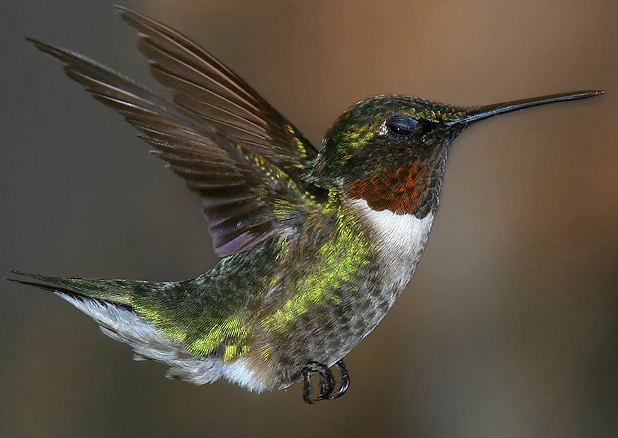
Fig. 2.6.1:
Photographing hummingbirds in flight without autofocus
is virtually inconceivable. Even with autofocus and proper
lighting,
much of hummingbird photography is pure luck.
Because different camera models can differ quite
substantially in their AF capabilities, understanding the basics of the
underlying technology can help you to better choose a camera that will
deliver more in-focus (and therefore “sharper”) photos of birds. Our goal in this section is to
develop a basic understanding of the different types of autofocus
systems in use today by the major players in the DSLR arena, so that
you can intelligently choose between them so as to suit the type of
bird photography you want to do. Understanding this material will
also be very useful later (in Part II of this book) when we discuss
techniques for obtaining the sharpest possible images in the field.
2.6.1 How
Autofocus Works
First, we need to understand a few
things about how lenses
work—in particular, about how they
focus an image onto a film plane
or a digital sensor. Since lenses are discussed in much greater
detail in the next chapter (Chapter 3), the description that follows
will be appropriately brief.
How A Lens Focuses an
Image
You probably remember from high-school physics that when a ray of light
(i.e., a stream of photons
all traveling in a single line) strikes a glass surface, it is refracted, meaning that the ray of
light changes its angle slightly. For the simplest optical
lenses, which are shaped in somewhat of an oval (or biconvex, parabolic) shape, this
means that light rays originating from the same point but following
different paths to the lens will be bent so as to reunite at some
particular point on the other side of the lens.
In Figure 2.6.2, below, you can see this illustrated
by the red lines, which represent light rays originating at some point
on the bird’s head, passing through the lens at different locations,
and then finally intersecting at some common point in the focal plane on the far side of the
lens. The blue lines in the figure also originate at a common
point on the bird’s leg, and also rejoin at a common point in the focal
plane, despite having taken different routes through the lens (the “focusing element” shown in the figure). The
property that light
rays originating at a single point, but following different paths
through an idealized, biconvex
lens, will under ideal conditions rejoin at a single point on a common
plane some distance beyond the lens is a basic mathematical result
deriving from the geometry of lenses.
If you were to place your head in such a position
that the retina of your eyeball was perfectly superposed over the focal
plane as defined by the geometry of a given lens (and the position of a
given subject imaged by that lens), you would perceive a perfect view
of the subject, though the image would be upside-down (this is a minor
detail that we’ll ignore from here on, since the electronics inside a
camera can easily deal with this issue by swapping all the pixels in
the image from top to bottom; we’re also ignoring the natural lensing
properties of the human eye for this discussion). If, however,
you were to stand slightly forward or backward from this ideal
position, so that your retina did not perfectly coincide with the lens’
focal plane, the image you perceived would be blurry.
To see why this is the case, note first that the
rays of light which converge at the focal plane in Figure 2.6.2
continue on past that plane, diverging from each other and producing a
scattered image on an imaging sensor placed some distance behind the
focal plane. This scattering of the rays of light which
originated at the same point on the bird distribute the color
information from that part of the bird over a wide region of the
imaging sensor, rather than focusing it at a single point. That’s
why the resulting image is a blur. The problem is that the
imaging sensor is not positioned at the focal plane. If it was,
the rays of light would properly converge and the image received would
be a sharp representation of the subject in focus.
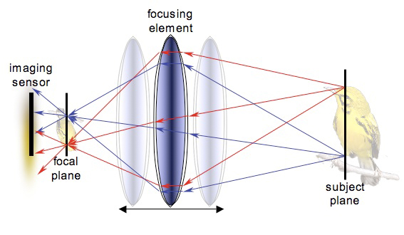
Fig. 2.6.2:
Focusing and Focal Planes.
Rays of light originating from particular points on the subject (right)
are
focused at corresponding points in the focal plane (left). When
the focal plane
does not coincide with the imaging sensor, a blurred image is received
(left).
By moving the focusing element (center), the focal plane can be shfited
so
as to coincide with the imaging sensor, thereby producing an in-focus
image.
In order to rectify this problem, we’d need to move either the imaging
sensor, the focal plane, or the bird. Given that most birds don’t
follow commands very well, the latter option can generally be ruled
out. Likewise, since the imaging sensor in a DSLR is generally
mounted in a fixed position within the camera housing, moving the
sensor is out of the question too. The remaining option is to
move the focal plane, and this we can easily achieve by moving the
focusing element.
In practice, camera lenses typically contain many
optical elements (each of which we would typically call a “lens”, but
which we’ll call an “optical element”, to avoid ambiguity). Some
of those optical elements can move, and this is how the lens is able to
focus on objects at different distances from the lens. In the
figure above we’ve simplified the scenario by assuming there’s just one
focusing element within the lens assembly. As that focusing
element is shifted toward the imaging sensor or away from it, the focal
plane also shifts. It’s important to understand that the focal
plane is defined by the position of the subject, relative to the
position of the lens. By appropriately adjusting the focusing
element inside the lens, we can shift the focal plane of a particular
subject so that it coincides with the imaging sensor, thereby producing
a perfectly in-focus image of the bird. This is, at the grossest
level, how autofocusing works: it shifts the focusing element until the
image focused on the sensor appears as sharp as possible.
AF
Sensor Points
The autofocus modules used in DSLRs don’t assess the sharpness of the
entire image when they’re adjusting the focus. Since the image is
made up of literally millions of pixels, accurately assessing image
sharpness (i.e., “in-focusness”) for the entire image would
require too
much work for the tiny computer chips embedded in the camera.
More importantly, since a tiny bird like a warbler typically doesn’t
fill the entire viewing frame, we’d like to be able to tell the camera
to just make sure that the bird is in focus, even if the surrounding
scenery isn’t. The way that we do this is via autofocus sensor points.
If you look into the viewfinder of a DSLR camera you
should see a set of black squares spanning the viewing field, as
illustrated in part A of Figure 2.6.3, below. These indicate
(roughly) the positions of the autofocus sensors. For any
particular camera model, the exact number and arrangement (and sizes)
of these AF sensor points can differ to a greater or lesser extent from
the one shown in the figure, which is based on the Canon pro-sumer line
of DSLRs. The pro models of both Canon and Nikon have many more
AF points, and those points are typically much more accurate at
assessing focus than those on the consumer and pro-sumer bodies, as
we’ll discuss later.
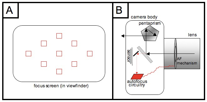
Fig. 2.6.3:
Left: a typical focus screen, as seen through the viewfinder.
Squares
represent AF sensor points. Right: how the AF system fits into
the overall SLR
architecture. Some light passes through the semi-transparent main
mirror and is
diverted to the AF system, which analyzes the image and then sends
electronic
commands to the focusing motor in the lens, so as to adjust focus.
In most camera bodies, it’s possible to select an individual AF point
to use for autofocus, or to utilize all of the points
simultaneously. For bird photography, the former (single AF
points) is typically best for stationary birds, while the latter (all
AF points in use simultaneously) is typically most useful for birds in
flight, though there are exceptions to both of these
generalizations. We’ll discuss strategies for choosing AF points
in much greater detail in section 6.6.
For now we’ll limit our
discussion to the case in which a single AF point has been chosen to
perform the autofocus function. In that case, the other AF points
are disabled, and all focusing information comes from the single AF
point that we’ve selected.
In part B of Figure 2.6.3 (above) we show the
overall structure of the camera’s light path. Recall that during
focusing, a portion of the incoming light passes through the
semi-transparent main mirror, and is diverted downward to the autofocus
circuitry located (typically) at the bottom of the camera. For
whichever square box you’ve selected in your viewfinder, there is a
corresponding AF sensor in the autofocus module that will be active
during focusing. Our goal in the sections that follow will be to
explain how that AF sensor is able to assess the sharpness (or “in-focusness”) of that part of the scene
(hopefully the bird) that the
AF square is positioned over. Once that focus information has
been collected by the AF sensor, the rest of the autofocus circuitry
then decides what needs to be done in order to bring the subject into
better focus, and we’ll discuss below how this happens too.
The actual process of adjusting the lens’ focus is a
mechanical issue, which we’ll largely ignore for the present. As
we’ll discuss later, there are some important differences in the
methods used by various lenses for moving their focusing elements,
including methods that rely on in-camera versus in-lens motors, and
also methods that rely on gears versus ultrasonic vibrations to move
the focuser. First, we’ll focus (no pun intended) on the AF
sensors, and how they differ between DSLRs and point-and-shoot cameras.
Contrast-based Autofocus
In compact, point-and-shoot cameras (including a few DSLR-like models),
the method used by the AF circuitry for selecting the best positioning
for the focusing element is to search for the most contrasty image. That is, the
camera shifts the focusing element back and forth, observing how the
movements of the focusing element affect the image’s contrast, and then
(eventually) settles on the focus setting that produces the image with
the highest contrast. This is largely a process of trial and
error, and can be quite slow—typically too slow for serious
action
scenarios. For this reason, DSLRs use a faster method called phase detection or phase comparison, which we’ll
describe shortly.
To see how contrast can guide the camera in focusing
an image, consider the series of images shown in Figure 2.6.4,
below. These images show a portion of a Prairie Warbler’s face,
including the bird’s eye and two black stripes below the eye. The
images are blown up so that the individual pixels are apparent.
The leftmost image is in focus, while the images to the right have been
progressively blurred in software, to simulate the effect of taking the
lens increasingly out of focus.
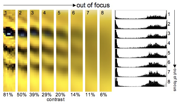
Fig. 2.6.4:
Simulated effect of focusing error on the perceived image.
Left: progressively out-of-focus images show less detail, as can be
measured by local contrast. Right: taking an image out of focus
can
result in a more peaked intensity histogram, as the image becomes
more homogeneous.
Below the images are contrast measurements, which are simply the
average intensity differences between all neighboring pixels, expressed
as a percentage of the maximum intensity (and then re-scaled by a
factor of 10). The important point is that the contrast measure
used here is based on local
differences in pixel intensities, where the intensity values reflect only the brightness of a pixel, not the hue (i.e., color). You can
see that, based on brightness alone, the contrast decreases very
rapidly as the bird is taken slowly out of focus, so that an in-focus
maximum contrast of 81% decreases to only 6% when the bird is taken
completely out of focus. The exposure
histograms on the right side of Figure 2.6.4 show that the luminosity (brightness)
distribution in the image becomes more “peaked”, or concentrated (i.e.,
less uniform) as the image is
taken out of focus, indicating a loss of “information” (or what
computer scientists call entropy).
The horizontal axis of these exposure histograms corresponds to
different levels of brightness—from very dark at the left end to
very
bright at the right end. The vertical axis represents frequency,
so that higher peaks in the graph mean that that particular brightness
value occurred more often in the image than other brightness values.
Note that although the second image is only slightly
out of focus, the measured contrast is over 30% less than for the
in-focus image. Local contrast (i.e., differences in intensity
between neighboring pixels) can thus be a very sensitive indicator of “in-focusness”, and explains why contrast-based
focusing systems,
despite being slow, can be very accurate. The problem with
contrast-based systems is that the contrast measurement gives no
indication of the direction
in which the lens element needs to be moved, nor the amount by which it
would need to be moved in that direction in order to achieve perfect
focus, so that the focusing circuitry has to adopt a trial-and-error
approach to finding the correct focus. Most DSLRs therefore use a
more sophisticated approach, called phase
comparison, which we describe next.
Phase-based Autofocus
The phase-based approach utilizes a neat “trick” arising from the
geometry of light paths through a simple lens. Consider a bird’s
eye—typically the most important
feature of a bird when adjusting
focus. Ambient light rays can strike the bird’s eye from any
direction, and they will reflect off of the bird’s eye in just as many
directions. As shown in Figure 2.6.5, below, those rays coming
from the bird’s eye that happen to strike the lens (focusing element)
are refracted upon entering
and leaving the glass element so as to be focused on a single point
inside the camera. Assuming that we’ve selected a particular AF
sensor point and positioned that point over the bird’s eye in the
viewfinder, the rays of light coming from the bird’s eye should pass
through the opening in the AF point screen (at left in Fig. 2.6.5)
corresponding to that selected AF sensor point.
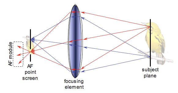
Fig. 2.6.5:
Overall structure of a phase-based AF system (with mirrors omitted,
for clarity). Light from the selected region of the scene passes
through the
corresponding aperture in the AF screen and into the AF module for that
selected AF point. The width of the cone of light passing into
the AF module
varies based on whether the subject is front-focused or back-focused.
If the focusing element is correctly positioned, the “eye light” (light
rays from the bird’s eye) will be focused precisely at that opening in
the AF screen, as suggested by the figure. After passing through
that focal point, they will again spread out in a cone. That cone
of “eye light” passes into the AF module shown
at left in Figure 2.6.5.
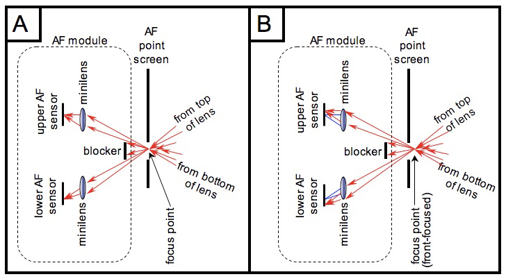
In Figure 2.6.6, below, we show an expanded view of
the AF module. In part A, in which the bird’s eye is perfectly in
focus, the light rays pass through the AF point screen, and are either
blocked by a “blocker” element or are captured by one of
two “mini-lens” elements (which may be
implemented as prisms in some
designs). The blocker element ensures that the only rays of light
reaching the minilenses are those which passed through either the
uppermost portion of the main lens or the bottommost portion.
Those from the bottommost portion end up reaching the upper minilens
and are then focused on the upper AF sensor positioned behind that
minilens, and conversely for the rays coming from the uppermost portion
of the main lens.
Fig. 2.6.6:
Detailed view of phase-based AF module. Light rays from the top
and bottom
of the main lens are separately re-focused onto twin sensors, and the
resulting images are
compared to determine the precise amount of front-focusing or
back-focusing in effect.
From this the AF system can determine how much the focusing element
needs to be adjusted.
In part A of Figure 2.6.6, we show the case for a subject that is
perfectly in-focus. The split light path forms two identical
images, one on the upper AF sensor, and one on the lower AF sensor
(both of these “AF sensors” correspond to a single “AF sensor point” as
viewed in the viewfinder, not to two different AF sensor points).
But notice how the light rays striking the upper AF sensor are angled
upward, while those striking the lower AF sensor are angled
downward. That’s important.
In part B of Figure 2.6.6, we show the case where
the focusing element is slightly mis-positioned, so that the bird is
slightly front-focused (i.e., the empty space in front of the bird is
in focus, but the bird itself is more-or-less out of focus). In
this case, the light rays striking the upper AF sensor will be shifted
upward somewhat from their normal position, while those striking the
lower AF sensor will be shifted slightly downward (the blue lines in
part B of the figure show where the light rays would be if the focus
had been set correctly). The images formed on the two AF sensors
will still be roughly identical, but the distance between the two
images, as measured along the AF sensor plane, will be larger than
expected for an in-focus image. This condition of
larger-than-expected distance between the two images indicates a
front-focusing condition. Had the bird instead been back-focused,
the two images would have been somewhat closer to each other than
expected. Thus, by measuring how much the images are shifted on
the paired AF sensors, and in which direction (i.e., closer or further
away from each other), the AF circuitry can determine both the
direction and the amount by
which the focusing element needs to be moved in order to achieve “perfect” focus.
Now we need to explain in greater detail some things
that we glossed over in the preceding discussion. If you’re
satisfied with the explanation given above, you can skip to the next
section, titled “Practical Consequences”. Otherwise, just keep
reading.
The first “fine point” we’ll consider is the issue
of how the AF sensor is able to measure the distance between the two
images formed on the twin AF sensors for a given AF sensor point.
Obviously, the computer chips inside the camera don’t know that you’re
photographing a bird, so they can’t find the bird in the two images and
measure the distance between them. What they can do, fairly rapidly in fact, is
to compare the intensity profile
along a single row or column of pixels with the corresponding profile
from the other AF sensor. In most DSLRs today, the individual AF
sensors are exactly that: a single row or column of pixels oriented
horizontally or vertically. If you imagine the thin image strips
we showed earlier in Figure 2.6.4 (above) being thinned down to a
single column of pixels, then you’ll have some idea of what the AF
sensors actually see, except that that the pixels would be seen in
shades of gray since color information is typically not used by AF
sensors.
In Figure 2.6.7 (below) we consider the task of figuring
out how much the twin images on the paired AF sensors are shifted
toward or away from each other, for the case where the sensors are
horizontal rows of pixels. In part C of the figure you can see
that the image is indeed slightly out of focus, because the two images
are shifted by about one pixel from each other (a half pixel in each
direction), so that properly aligning the two images requires an
overhang of one pixel on each end. Obviously, this comparison is
done electronically in the camera; we’ve arranged the pixel arrays
side-by-side in the figure just to make it easier for you to compare
them visually.
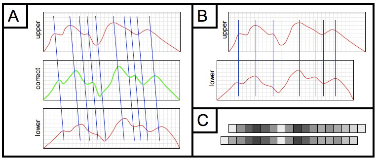
Fig. 2.6.7:
Image registration in phase-based AF systems. (A) A front-focused
subject
produces two intensity profiles (red) which are shifted and deformed
relative to the
correct (and unknown) profile shown in green. (B) The optimal
correlation of intensity
profiles. (C) Actual pixel intensities for the two sensors, and
their optimal alignment.
In part A of the figure we show the intensity
profiles of the twin AF sensors (marked “upper” and “lower” in
the figure) as graphs, where the height of the curve at any point shows
the intensity (brightness) registered by that pixel (don’t confuse
these intensity profiles with the exposure
histograms shown in Figure 2.6.4; in these profiles, the
horizontal axis corresponds to pixels in the AF sensor, whereas in the
exposure histograms the horizontal axis corresponds to different
brightness levels). The green curve in the middle shows what the
profile would look like if the image had been in perfect focus.
As you can see, because the image is out of focus, the upper profile is
shifted one way and the lower profile is shifted the other way.
Of course, the green curve isn’t available to the camera, so the camera
has to compare the upper and lower profiles directly. In part B
we show the two profiles aligned so that their peaks and valleys line
up. In order to make the peaks and valleys line up, we had to
shift the upper profile to the right by some distance. Once the
camera figures out this distance, it can compute the exact amount (and
direction) that the focusing element in the lens needs to be shifted in
order to bring the image into perfect focus (or near-perfect
focus—see below). Thus, the two
curves are considered to be out of
phase by some amount, and this amount of phase difference is a measure of
how out-of-focus the image is, and in which direction. Hence the
term phase-based autofocus.
So, all the camera has to do is to find the best
alignment of the two profiles in order to deduce how much the images
are shifted relative to each other (and in which direction—i.e.,
whether they’re shifted away from each other or toward each other,
corresponding to front-focusing or back-focusing). This is
sometimes referred to as the problem of image registration. How can
the camera find the best alignment between the two profiles? And
how can it do so very, very rapidly? Precisely how this is
implemented in a given camera model may differ, but a straightforward
technique is to have an array of parallel circuits each of which
computes a correlation score for a
particular alignment of the two profiles. For example, one
subcircuit would compute the correlation for the two profiles aligned
with a shift of one pixel to the right, another would compute the
correlation for a shift of two pixels, another for a shift of three
pixels, etc. Circuits would also be included to handle shifts in
the other direction. These circuits all compute their correlation
scores simultaneously, and the circuit producing the highest
correlation score dictates the optimal offset for the alignment, and
therefore the desired adjustment for the focusing element. These
correlation scores (or a similar score called the coefficient of determination)
can be computed almost instantaneously using analog circuitry that
combines solid-state elements for multiplication and addition. In
this way, phase-based AF methods are generally unrivaled in their
capacity for raw speed.
Another fine point requiring a brief explanation is
the slight difference in the shapes of the profiles shown in part B of
Figure 2.6.7. Not only are the two curves shifted relative to
each other, but their peaks and valleys are somewhat deformed relative
to each other. In fact, if you compare these two profiles to the “correct” profile for an in-focus image
(the green curve in part A of
the figure) you’ll see that the peaks and valleys have been somewhat
eroded and skewed. This is because the twin images for these
profiles have each become somewhat out-of-focus (remember, the main
image itself is front-focused in this example), but since the paired AF
sensors receive light rays from different parts of the main lens (as we
showed previously, in Figure 2.6.6), the image data will be “smeared”
in opposite directions in the two images. For this reason, the
twin images won’t look exactly the same, and neither will their
intensity profiles, which is why the correlation score is needed to
find the best alignment between the profiles, since there generally
won’t be a “perfect” alignment between them.
Note, however, that
the degree of distortion in the twin images due to being out-of-focus
can be mitigated by using a relatively small aperture in the AF
minilenses. As we’ll eventually discuss in section 6.1, using a
small aperture results in greater depth-of-field
(DOF) which in turn allows slightly out-of-focus images to appear more
in-focus.
Other assumptions of the phase-based system that
we’ve largely glossed over up till this point are that the subject is
parallel to the sensor plane (so that the portion visible through the
AF sensor point is either completely in focus or completely out of
focus) and that there are no intruding elements (such as twigs or
branches) passing in front of the subject. In practice, these
assumptions can often be violated to varying degrees without
catastrophic results, but in order to obtain the most accurate
performance, especially in poorly-lit scenes, it’s good to try to keep
these considerations in mind. Whenever possible, it’s best to
avoid focusing on a part of the bird that isn’t oriented as a flat
surface parallel to the sensor plane, or to focus through intervening
foliage. Even if you think there are enough “windows” through the
foliage to get a good exposure of the subject (i.e., with intervening
foliage being rendered out-of-focus and nearly invisible in the final
image), the greater depth-of-field of the AF sensors’ mini-lenses can
result in the autofocus module being more confused by the intruding
elements than you might otherwise expect, based on your view through
the viewfinder.
Note that while the phase-based AF technique is in
theory capable of moving the focusing element directly to the precise
location needed to achieve perfect focus, without the need for any “searching” as done in the contrast-based
method, in practice some
fine-tuning of the focus can be necessary even with phase-based AF, due
to slight measurement errors in the distance calculation. Another
source of error in the phase-based system is imperfect factory
calibration. Because phase-based systems are much more
complicated than contrast-based systems, they require precise
calibration in order to work correctly. Both Canon and Nikon are
known for selling cameras that are not always perfectly calibrated at
the factory and need to be sent in to the manufacturer’s service center
for re-calibration. Even the pro models from these companies are
not immune to this: a recent “voluntary recall” by Canon of its $4000
pro body (the 1D Mark III) was carried out due to faulty calibration of
some of the outer focus points in select units of that model.
This is one of the hidden costs of the increased complexity of these
systems.
It should be noted that while DSLRs generally use
phase-based autofocus instead of the simpler contrast-based method,
there are a few exceptions. The first exception occurs in the
context of Live View.
Recall from section 2.1.2 that Live View
is a mode of operation which
is increasingly becoming available on DSLRs, in which the shutter is
left open and the image formed on the main image sensor is shown in
near-real-time on the camera’s back LCD screen. The first
generation of live view capable DSLRs required manual focusing when
using live view, but newer models now allow the user to invoke a
contrast-based autofocus function when in live view mode. The
reason phase-based autofocus can’t be used during live view is that the
light path can’t be split during exposure so as to direct some of the
light to a dedicated AF module with paired AF sensors as required for
the phase-comparison method. The other notable exception is the new
crop of “compact” DSLRs and DSLR-like cameras being
offered by various
second-tier and third-tier companies which utilize contrast-based
autofocus. These cameras, unfortunately, mostly use the so-called
four-thirds
imaging form factor, which involves a 2x crop factor and therefore
limits photosite sizes and places limits on the noise characteristics
of the sensor.
Practical Consequences
Now let’s consider how knowing any of this can help
you to either choose a better camera (if you’re in the market for a new
one) or to operate your existing camera better. First, regardless
of whether a camera uses contrast-based or phase-based AF technology,
the subject you’re trying to focus on needs to have some contrast in
order for the camera to properly focus on it. This is obviously
true in the case of contrast-based AF methods. In the case of
phase-based methods, the intensity profile as seen by the twin AF
sensors (i.e., part B in Figure 2.6.7) has to have some peaks and
valleys in it, or the correlation score will be useless for aligning
the two profiles.
Keep in mind that the autofocus procedure is applied
only to the portion of the image covered by the selected AF sensor
point(s). If the bird is either large or very close and the AF
sensor point is positioned over a part of the bird that is of a uniform
color and has no visible contrast, then both methods described above
will usually fail. Remember also that the actual AF sensors are,
in most DSLRs, just a single strip of pixels oriented either
horizontally or vertically. If your subject (or the part of your
subject you’re trying to autofocus on) has visible features that are
parallel to the AF sensor’s pixel array, rather than perpendicular to
it, then autofocus will again tend to fail. For example, if the
AF sensor point you’ve selected is a horizontal-type sensor and you’re
trying to focus on a part of the bird that has horizontal bars and
nothing else, then the intensity profile seen by that AF sensor point
won’t have any strong peaks or valleys (no contrast), and the
phase-comparison method will fail because the twin profiles have no
strong features that can be aligned.
Many pro and pro-sumer cameras, and now even some
consumer-grade cameras, feature one or more cross-type AF sensors, in
which the
sensor has both a vertical array of pixels and a horizontal one, so
that the problem just described shouldn’t happen as often.
Unfortunately, these cross-type sensors are typically limited (except
in pro bodies) to just the central AF point, with all other AF points
being strictly horizontal, or strictly vertical. Furthermore, in
many cameras having one or more cross-type sensors, these sensors
typically revert to working as strictly horizontal or strictly vertical
whenever the main lens has a maximum aperture smaller than f/2.8 or so, meaning that most
consumer-grade lenses force the cross-type AF points to lose their
cross-type functionality. One way around the horizontal/vertical
AF sensor problem is to rotate your camera 90 degrees whenever focusing
a subject with strong horizontal or vertical bars/stripes. It’s
therefore good to know which types of AF sensors (horizontal or
vertical) are in your camera, and/or to know which sensors are of which
kind (if your camera has both), in case you find a strongly striped or
barred bird and have difficulty getting the camera’s autofocus to lock
on to the bird in either portrait or landscape orientation.
Finally, the above discussion highlights two reasons
why you should always try to choose lenses with the largest aperture
(smallest f-number).
First, a larger aperture will obviously let in more light, and any
contrast that is present in the subject will be better captured and
more effectively utilized by the AF module when more light is
collected. Note that what we’re talking about here is the maximum aperture of the lens, not
the aperture used for actually taking the photograph. An f/2.8 lens can of course be “stopped down” to f/11 in
order to produce an image with greater depth-of-field, but the actual
stopping-down to f/11 doesn’t
happen until the mirror flips up and the shutter opens (stopping-down is discussed in
detail in Chapter 6). During autofocus, the aperture is always
kept wide open, so what matters is the maximum aperture that the lens is
capable of opening up to, not the aperture setting that you dial in on
your camera for a particular exposure.
Second, for the phase-based AF method, recall that
the twin AF sensors in each AF sensor point collect light from opposite
sides (top and bottom, or left and right) of the main lens, and they
utilize the difference in angles between these two sets of light rays
to deduce the correct AF adjustment. For lenses with a maximum
aperture of f/5.6 or f/8 or f/11, the rays of light coming from
opposite sites of the lens aren’t forming such wide angles as they
would if you were using an f/2.8
or f/4 lens. This means
that the shifting of the intensity profiles from the twin AF sensors as
described above and illustrated in Figure 2.6.7 will be reduced to
smaller distances that will be harder for the camera to detect and
precisely measure. For very small (maximum) apertures like f/11 or f/16, the shifting of the intensity
profiles can be so small that the camera may not detect it at
all. In fact, most consumer-grade and pro-sumer cameras won’t
perform autofocus at all for lenses having a maximum aperture of less
than f/5.6 (which is one
reason why the use of teleconverters on many lenses causes autofocus to
be disabled). Pro cameras can typically perform autofocus with
lenses having a maximum aperture of f/8,
but not with lenses having smaller maximum apertures like f/11 or f/16. Even if your camera
does support autofocus at f/5.6
or f/8, in poorly lit
conditions the combination of low light levels and reduced profile
shifting distances due to shallow light angles can severely affect the
accuracy of the autofocus.
Remember that in phase-based systems, the total
amount of light passing through the main lens is severely reduced
before it reaches the AF sensors: it’s first reduced by the tiny “window” in the AF screen corresponding to
the selected AF point, the
portions coming from the middle part of the main lens are blocked out,
and then the remaining light is split (i.e., halved) between the upper
and lower (or left and right) AF sensors. This is why autofocus
in low-light conditions is very difficult for DSLRs, and why using a
lens with a large maximum aperture can very profoundly affect the
ability of the camera to accurately perform autofocus.
Mechanical Considerations
As we mentioned earlier, there are
a few mechanical issues related to the implementation of autofocus in
different cameras and lenses that may be of interest to the aspiring
bird photographer. The first is whether the motor that moves the
focusing element is located within the camera or in the lens.
Most lenses today have the motor located inside the lens assembly, but
some older lenses (such as Nikon’s 80-400mm VR zoom lens) utilize a
motor located inside the camera. In the latter case, the camera’s
AF motor articulates (connects) to the focusing element in the lens via
a long rod that spins like a motorized screwdriver, clockwise to focus
out and counterclockwise to focus in. The motor-in-the-body
solution has been largely abandoned by the leading manufacturers
because having a dedicated motor embedded within each lens, while
seemingly redundant, does allow for much faster and perhaps more
accurate control of the focusing element.
Another technological innovation is the use of ultrasonic motors (USMs) for
focusing, which utilize vibrations to turn the motor drive.
Though Canon pioneered this approach and uses it in all of its large
telephoto lenses, other manufacturers have followed suit with their own
versions of the technology, under a variety of different names—i.e., hypersonic motor (HSM) by Sigma, silent wave motor (SWM) by Nikon,
etc. The advantages of USM-type motors are the near silent
operation of the motor (which can be important when working in a
bird-blind or similar close-quarters situation, where birds may be
scared away by mechanical noises), and sometimes a faster and possibly
more accurate control of the focusing element, which can obviously be
important as well.
2.6.2 One-shot
Versus Servo
Most DSLRs offer two main AF
modes: one-shot, and servo (or continuous AF). The former,
one-shot, is for static subjects, while continuous AF (servo) is for
shots of subjects that are in motion. With one-shot, the camera
attempts to achieve focus of the subject and then beeps after focus has
been achieved. At that point, the AF module basically goes to
sleep; if the subject suddenly moves, the camera will not re-focus the
lens so as to re-establish focus. If the subject moves out of the
focus plane after one-shot has finished focusing, you need to
re-initiate focus by lifting your finger from the shutter-release
button and pushing it back down (halfway) so that one-shot AF starts up
again and then beeps to confirm that it has regained focus. In
servo mode, the AF module never goes to sleep, as long as you have your
finger on the shutter-release button (i.e., holding it down
halfway). As soon as the bird moves, the AF module will detect
that the image is no longer in focus and will take action to restore
focus. For birds in flight, servo is essential for keeping the
bird continuously in focus throughout its trajectory.
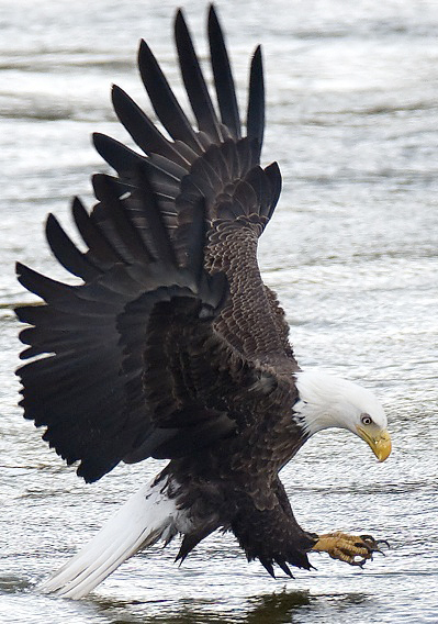
Fig. 2.6.8:
Reliable, continuous AF ("servo") is invaluable for
action shots. A camera with good servo will keep the bird
in focus during most or all of its flight, allowing you to
concentrate on capturing the ideal moment .
Note that servo can also be used for stationary
subjects, and one-shot can sometimes be used for subjects that are not
completely still. When photographing warblers I often use one-shot
instead of servo, even though these tiny birds are almost always
moving. As long as the bird stays perched in one location,
one-shot can be used to focus on the bird because its movements (e.g.,
eating, stretching the wings, etc.) are not taking the whole bird in
and out of the focus plane. Conversely, when photographing a bird
that is currently stationary but that might suddenly take flight, I’ll
often use servo, since servo can (usually) work just fine on stationary
subjects, and will obviate the need for me to quickly switch focus
modes when the bird suddenly leaps into the air. Just note that
on some bodies, the servo mode might be “jumpier” than on others, so
that for a stationary subject the AF module might constantly invoke
tiny changes in focus as it searches for a better focus of the
stationary bird. Some units of Canon’s current pro body, the 1D
Mark III, exhibited this type of “jumpy” behavior when using servo mode
for stationary subjects, until Canon corrected the behavior via a firmware update (i.e., an update to
the software running on the tiny computer inside the camera that
controls various camera functions such as autofocus).
The accuracy of servo mode can differ substantially
between camera models. Whereas some models feature a “predictive”
servo, which actively tries to predict the trajectory of the subject in
order to more closely track it during focusing, others are more “reactive” in that they wait to re-adjust
the focus until they detect
that the subject has already moved. Reactive servo can suffer
from poor tracking, because the AF module is always “playing
catch-up”. Predictive servo tries to
act more intelligently by
incorporating an additional correction factor into its focus changes,
so as to account for the subject’s velocity relative to the
camera. For birds flying erratically, however, this predictive
approach can fail because the camera overcompensates and behaves too
confidently in its prediction of the bird’s next location. The
best way to assess the effectiveness of these various technologies is
to test them out in the field yourself, or to wait until a camera is
professionally reviewed by an online magazine or product review site
that will test the camera on moving objects. Unfortunately, many
of these review sites test their cameras on either athletes or moving
vehicles, rather than birds.
2.6.3
Customization and Special
Settings
One important difference between
various camera bodies is the degree to which the AF system’s behavior
can be customized to suit your shooting style. For most
consumer-grade and pro-sumer bodies, little or no customization is
possible. In contrast, pro bodies typically offer many options
that can be set via the camera’s “custom functions” menu. So many
options are available on some pro bodies, that many users—even pro
users—don’t know what all of the options
do. We’ll briefly
review some of the options that are typically offered on current pro
bodies, so that you’ll know what to look for when reading up on a
prospective model’s features.
An important option for photographing birds in
flight is the ability to adjust the camera’s sensitivity to large
changes in focus during servo tracking. This comes into play when
you’re tracking a bird in flight and you momentarily allow the AF
sensor point to slip off of the subject in the viewfinder. This
happens a lot when tracking erratically flying birds, especially when
you’re hand-holding a lens (i.e., not using a tripod), since smoothly
tracking a bird in your viewfinder can be quite difficult for
fast-moving subjects, or when the subject quickly changes
direction. Turning down the tracking
sensitivity gives you more time to re-acquire the bird in your
viewfinder, because the camera pauses for a longer interval when it
detects a large change in focus. This can also be useful when
tracking a bird that may fly behind a tree branch or telephone pole;
with a low enough sensitivity setting, the camera won’t try to focus on
the branch or pole, but will instead wait for the bird to come back
into view.
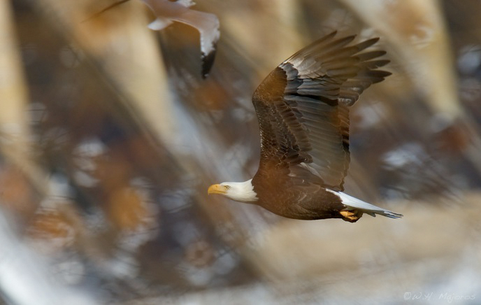
Fig. 2.6.9:
Bald eagle through fairly dense foliage. Although the foliage is
rendered out-of-focus by the wide aperture of the telephoto lens, it
can still
confuse the autofocus system. By setting the tracking sensitivity
to a low value,
I was able to continue tracking this eagle even after it flew behind
the foliage.
Another
important option for birds in flight (BIF)
is to allow the camera to switch to nearby AF points when the subject
has drifted off of the selected AF point. This is sometimes
referred to as AF point expansion.
In the case of simple expansion, the camera may allow you to restrict
expansion to any immediately neighboring AF point, or to just those AF
points above or below the currently selected one, or perhaps to the
ones left or right of the current one. If instead of having a
single AF point selected you enable all
AF points, the camera may (depending on model) allow the subject to
drift to any AF point and keep tracking the subject there. In the
pro bodies you may also be able to fine-tune this behavior by
specifying, for example, what to do if two AF points register subjects
(or parts of the same subject) at different distances from the camera
(some cameras can indeed compute the approximate distance to a subject,
based on the setting of the focusing element).
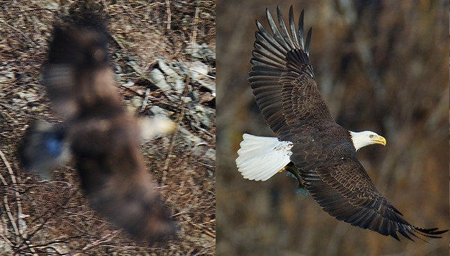
Fig. 2.6.10:
Left: when I let this bald eagle drift off of its AF point, the
camera refocused on the rocks in the background. Right: By
enabling AF
point expansion, I found that the camera was better able to keep the
bird in
focus even if it drifted momentarily off of the selected AF point.
Yet another
option on some bodies is whether the AF
system should keep searching for a subject by racking the focusing
element in and out, when a subject hasn’t yet been successfully
focused, or whether the AF system should give up after one search over
the full range of the focusing element. Though phase-based AF
systems are described as not requiring a search-based approach to
achieving focus (unlike contrast-based systems), that’s true only if
all of the assumptions are satisfied—i.e., the subject is parallel to
the focus plane and fills the whole AF sensor point, there are no
extraneous intruding elements in front of the subject, etc. Also,
if the subject is extremely out of focus when you first engage the
autofocus, a search is often necessary to find the “neighborhood” of
the correct focus, after which a direct focus adjustment based on the
phase-comparison method described above may be sufficient to jump
directly to the correct focus point.
Perhaps the most useful feature to recently emerge
in AF systems is the ability of users to calibrate the focus system via
the so-called AF microadjust
setting. As we remarked earlier, phase-based AF systems are
complex devices that require precise calibration at the factory.
Many cameras, especially consumer-grade models, are only roughly
calibrated at the factory, with fairly liberal “tolerances” in
component settings. For example, I’ve read that consumer-grade
models are typically calibrated with a tolerance of +/- one DOF
(depth-of-field), whereas pro bodies are generally calibrated with a
much more exacting tolerance of +/- one-third DOF or less. The AF
“microadjust” feature (for those cameras that
offer it) allows you to
calibrate the focusing system yourself, by dialing in a number
typically ranging from -20 to +20. This number is added in to the
camera’s focus computations so as to bias the setting of the focusing
element away from where the camera would normally set it. This is
useful if you find that your camera is consistently front-focusing or
back-focusing, because you can compensate by consistently adjusting the
focus one way or the other (backward or frontward),
automatically. On some camera models you can set a different
microadjust value for different lenses, to account for focusing biases
that are due to defects in the lens’ calibration rather than the
camera’s. Finding the optimal microadjust setting for your camera
is discussed in section 3.11.
References
Kerr, DA (2005) Principle of the Split Image Focusing Aid and the Phase
Comparison Autofocus Detector in Single Lens Reflex Cameras. URL:
http://doug.kerr.home.att.net/pumpkin/Split_Prism.pdf
|
|
|